

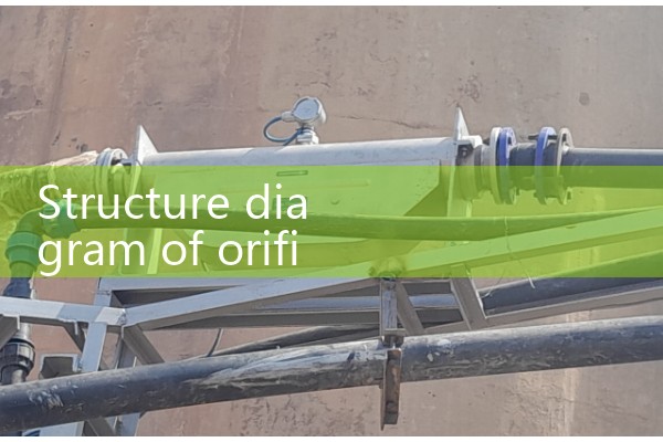
『Structural diagram of orifice flowmeter』Related information(clamp on meter|electromagnetic meter|venturi meterrotameter|orifice meter|ultrasonic flow meter|mass flow meter|coriolis mass flow meter|coriolis flow meter|magnetic flow meter|magmeter flow meter|magflow flow meter|mag meter flow meter|electromagnetic flow meter|vortex flow meter|turbine flow meter|thermal mass flow meter|thermal flow meter|rotameter flow meter)

What kind of flow meter is a steam flow meter orifice plate and what are its advantages?
The steam flow meter orifice plate is a type of differential pressure flow meter that is mainly used for gas and steam flow measurement. It has the advantages of high accuracy and good stability. In the process of steam seepage flow measurement, maintenance is not required, greatly improving the efficiency of on-site use..
2. Working principle of orifice flowmeter
An orifice flowmeter is a device that calculates gas flow by measuring pressure difference. Its core principle is based on energy conservation and flow continuity in fluid mechanics.
. Here is a detailed explanation:1. Working principle: When gas flows through an orifice plate, due to the sudden reduction in the cross-sectional area of the orifice plate, the gas flow velocity increases significantly at the orifice, while the pressure decreases. According to the Bernoulli equation, the kinetic energy and static pressure energy of a fluid are converted into each other, and an increase in flow velocity leads to a decrease in static pressure, thereby forming a pressure difference (Δ P) between the upstream (high-pressure side) and downstream (low-pressure side) of the orifice plate. The relationship between flow rate and pressure difference: Under stable flow conditions, the gas flow rate (qv) is proportional to the square root of the pressure difference (Δ P), that is: qv: gas volume flow rate (m3/min) K: orifice plate coefficient (determined by orifice plate geometry, gas properties, etc., calibrated at the factory) Δ h: water column pressure difference measured by U-tube (mm), multiplied by density ratio 13.6 if using mercury column.
2. Structure Composition: The orifice flowmeter consists of the following core components: orifice plate: a circular thin plate with a precisely sized circular hole in the center, which is a key component for generating pressure difference.
. Pressure nozzle: located upstream and downstream of the orifice plate, used to connect a differential pressure gauge (such as a U-shaped tube) and measure the pressure difference Δ h. Steel pipe and flange: form a gas circulation pipeline, and fix the orifice plate through the flange to ensure sealing. Auxiliary components: including sealing rings, connecting bolts, negative pressure gauges (monitoring pipeline pressure), etc.III. Specifications and Selection of Orifice Plate Diameter Selection: The size of the orifice plate is determined based on the estimated gas drainage volume and the range of water column pressure difference Δ h, and is enclosed (usually 100-1000Pa).
. Differential pressure measurement range: Δ h should be within the instrument range to avoid measurement errors caused by being too large or too small. 4. Installation and Use Requirements Concentricity and Verticality: The orifice of the orifice plate must be concentric with the pipeline, the end face must be perpendicular to the axis, and the eccentricity should be ≤ 1%~2%, otherwise it will cause flow disorder and affect the accuracy of pressure difference. Smooth inner wall of pipeline: There are no bumps, welds or gaskets within the 2D range (D is the diameter of the pipeline) before and after the orifice plate, reducing local resistance. Length of straight pipe section: Hot Product
 Related AD