

『Exair Flow Meter Installation Manual: Optimizing Air Compressors with Compressed Air Meters』Related information(clamp on meter|electromagnetic meter|venturi meterrotameter|orifice meter|ultrasonic flow meter|mass flow meter|coriolis mass flow meter|coriolis flow meter|magnetic flow meter|magmeter flow meter|magflow flow meter|mag meter flow meter|electromagnetic flow meter|vortex flow meter|turbine flow meter|thermal mass flow meter|thermal flow meter|rotameter flow meter)

Exair Flow Meter Installation Manual: Optimizing Air Compressors with Compressed Air Meters
Quick Answer: A compressed air meter shows real air consumption and helps you find leaks before they inflate the power bill. Install the meter with enough straight run and keep the sensor out of moisture pockets. Send Silver Automation Instruments your pressure bar, temperature degrees Celsius, pipe size DN, and flow range for a direct meter recommendation.
Why Compressed Air Measurement Is a Cost Problem
Compressed air is not free. It is one of the most expensive utilities in a plant. The compressor consumes electricity and then leaks, pressure drops, and artificial demand add extra cost. In many plants in Southeast Asia and the Middle East, 20 to 35 percent of compressed air is lost before it reaches the point of use. A paint manufacturer in Vietnam installed two insertion thermal mass meters and measured weekend demand. The data showed a 24 percent leak rate when production was shut down. That finding paid for the meters within four months.
Most engineers skip this part. They install a meter only at the compressor discharge and never measure branch lines. Without branch data you cannot see which production area wastes air. That is the difference between a meter and a real optimization project.
What the Exair Flow Meter Installation Manual Covers
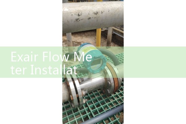
The Exair flow meter installation manual is a solid reference for compressed air meter setup. It covers sensor placement, straight run needs, pipe orientation, and leak trending. The same rules apply to most thermal mass flow meters used on compressed air lines. Silver Instruments provides similar installation guidance for our thermal mass and vortex meters. The manual helps a plant team avoid the worst errors, but it does not replace a proper process audit.
Installation Details That Change Your Readings
Straight run is the first item. For a thermal mass insertion meter, allow at least 15 pipe diameters upstream and 5 downstream from a bend or valve. For an inline vortex meter, 10 diameters upstream is often enough. More is always better. Ignore this and the flow profile will be unstable. You get a repeatable but wrong number.
Moisture is the second issue. Compressed air after a dryer is usually clean, but temperature changes can produce condensate in low points. Do not install the meter at the bottom of a horizontal pipe. A horizontal insertion point should be on the side of the pipe, roughly between the 9 and 3 positions viewed from the pipe end. If the pipe is vertical, upward flow is preferred because it keeps condensate moving away from the sensor.
Probe depth matters. For an insertion thermal mass meter in a DN80 pipe, the probe should reach the centerline. For larger pipes, use the manufacturer setting based on pipe inner diameter. Do not guess. Centerline placement works for many compressed air lines above DN50.
Thermal Mass or Vortex for Compressed Air
Thermal mass flow meters work well for compressed air and nitrogen because they measure mass flow directly. They do not need temperature or pressure compensation for a single gas. A thermal insertion meter handles DN50 to DN300 lines and gives you Nm3/h or kg/h output. Accuracy in the field is often around plus or minus 1.5 percent of reading with good installation. Vortex meters are another option for inline measurement from DN15 to DN200. They are strong in clean dry air and give you a frequency or 4 to 20 mA HART signal. If your line
Here is the thing. Most compressed air meters are ordered without enough process detail. A buyer says we need a compressed air meter. Then we ask pipe size, pressure, temperature, and flow range. Those four values decide the meter type, probe length, and output. Without them you get a stock device that may not fit.
Optimizing Air Compressors with Compressed Air Meter Data
One compressed air meter on the main header gives you total demand. A second meter on a branch line shows which production area uses air. Use the total demand trend to match compressors to load. For example, if a 75 kW fixed speed compressor runs at 40 percent capacity during the afternoon shift, a 37 kW variable speed compressor may handle that load with less energy. The meter data supports that decision instead of a guess.
Leak detection is easier with a compressed air meter. Measure flow during a shutdown or lunch break. If the header still flows 8 to 15 percent of peak demand with no production, you have leakage. A food packaging plant in Indonesia found 12 leaks around solenoid valves and fittings. The compressed air meter data narrowed the search from the whole plant to two branches. Maintenance fixed those leaks in one day.
Silver Instruments Meter Fit for Compressed Air Systems
Silver Automation Instruments supplies thermal mass flow meters with insertion probes, 4 to 20 mA HART, RS485 Modbus, and a local display. We also supply inline vortex flow meters for compressed air from DN15 to DN200. Typical pressure ratings are PN16 to PN40, and process temperature can go up to 120 degrees Celsius for standard models. For compressed air at 7 bar and DN100 pipe, a thermal insertion meter with 0 to 500 Nm3/h range is a common starting point. For a DN25 branch line, an inline vortex meter gives a cleaner installation.
Send us your pressure bar, temperature degrees Celsius, pipe size DN, and flow range. We will reply with a model suggestion, probe depth, and price. Contact Tel: +86-25-68650347, Whatsapp: +86-25-52155837, WeChat: +86 15365082610. You can also review our meter selection at flow-meter.com.au.
Frequently Asked Questions
Can a compressed air flow meter be installed in a vertical pipe? Yes. Vertical upward flow is generally preferred for thermal mass meters because moisture drains away from the sensor. Follow the same straight run rules.
What straight run is required for a compressed air meter? For a thermal insertion meter, keep 15 pipe diameters upstream and 5 downstream from any bend or valve. Inline vortex meters often need 10 diameters upstream and 5 downstream. More is better if space allows.
Does moisture damage the compressed air meter? Moderate moisture in the air stream is normal, but liquid condensate on the sensor can cause drift. Install the probe on the side of a horizontal pipe and above low points. Use a dryer and a filter upstream when possible.
What output should I request for compressor monitoring? Request 4 to 20 mA HART plus RS485 Modbus if you want local display and control room data. This covers most compressor energy management systems and SCADA packages.
Can one compressed air meter monitor multiple compressors? Yes. Place one meter on the main header after all compressor discharge lines combine. You will see total demand. For individual compressor performance, install separate meters on each discharge line or use one meter and sequence the compressors manually.
 Hot News
 Related AD