

 Current position > Product detail
『Small flow turbine flowmeter』Related information(clamp on meter|electromagnetic meter|venturi meterrotameter|orifice meter|ultrasonic flow meter|mass flow meter|coriolis mass flow meter|coriolis flow meter|magnetic flow meter|magmeter flow meter|magflow flow meter|mag meter flow meter|electromagnetic flow meter|vortex flow meter|turbine flow meter|thermal mass flow meter|thermal flow meter|rotameter flow meter)

1. Science popularization: Precautions for installation of turbine flowmeter
Turbine flowmeter (impeller flowmeter) is a high-precision instrument that uses turbine rotation for flow measurement. It has the advantages of simple structure, high temperature resistance, and long service life. Attention should be paid to the following key points during installation:
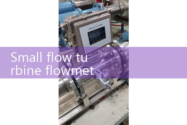
1. Installation method: The turbine flowmeter supports three installation methods, which should be selected reasonably according to the working conditions: flange installation: suitable for standard connections in pipeline systems, ensuring that the flange sealing surface is flat and the bolts are evenly tightened to prevent leakage. Threaded installation: Used for small-diameter pipelines (usually below DN50), attention should be paid to thread matching to avoid thread damage caused by violent tightening. Clamp on installation: suitable for temporary measurement or space limited scenarios, ensuring uniform clamping force to prevent sensor displacement. Figure: Typical installation structure of turbine flowmeter
2. Fluid direction control. Mandatory requirement for liquid measurement: The fluid flow direction must be completely consistent with the arrow direction marked on the sensor housing. Reverse flow can cause the turbine to reverse, leading to measurement errors and even mechanical damage. Gas measurement suggestion: Although there is no mandatory requirement, maintaining consistent flow direction can reduce turbulence effects and improve measurement stability.
III. Outdoor Installation Protection and Waterproof Treatment: When installing outdoors, the amplifier plug needs to be sealed. It is recommended to use a dedicated wate
Fourth, the pipeline system requires a straight pipe length: Upstream: It is recommended to be ≥ 10 times the pipe diameter (for pipes below DN100, it can be relaxed to 5 times). Downstream: It is recommended to be ≥ 5 times the pipe diameter to eliminate vortex interference caused by valves, elbows, etc. and avoid vibration sources. Keep away from vibration equipment such as pumps and compressors, and install shock absorbers if necessary.
. Temperature control: The temperature of the sensor body should not exceed the nominal value (usually -20 ℃~+80 ℃), and high-temperature resistant models should be selected for high temperature conditions.Fifth, Electrical Connection Specification Grounding Requirements: It must be reliably grounded with a grounding resistance of ≤ 4 Ω to prevent static electricity and electromagnetic interference.
. Cable selection: Signal line: Shielded twisted pair cable (such as RVVP 2 × 1.5mm2) Power line: Independently wired to avoid parallel connection with power cables Explosion proof area: In flammable and explosive places, intrinsically safe or explosion-proof instruments should be selected, and explosion-proof wiring specifications should be strictly followed. 6、 Debugging and acceptance zero calibration: After installation, static zero calibration is required to ensure that the output is zero when there is no fluid. Dynamic